| TORQUE: | 300 to 18,000 in-lb (34-2034 Nm) |
| VOLTAGE: |
VAC: 24, 120, 220 VDC: 24 |
| STANDARD ENCLOSURE: | NEMA 4, 4X and IP65 |
| EXPLOSION PROOF: |
NEMA 4, 4X Class I, DIV 1 & 2, Group C, D Class II, DIV 1 & 2, Group E, F, G |
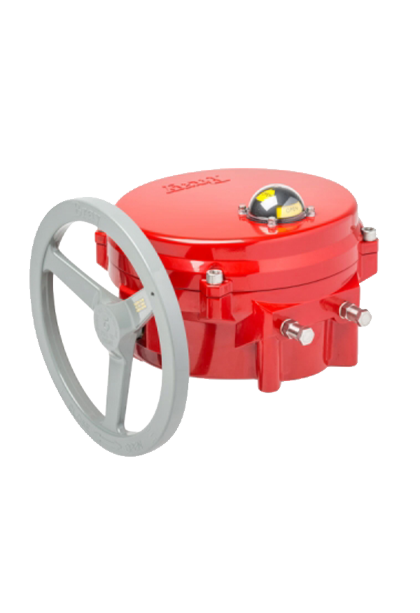
ELECTRIC ACTUATOR
Output Torque 300 in-lb (34 Nm) to 18,000 in-lb (2,034 Nm)
Bray Controls’ years of proven success in electric actuation, combined with innovative engineering, has produced the Series 70 electric actuator. The Series 70 features on/off or modulating control. Bray’s Series 70 electric actuator has many advantages over other actuators including:
- UL,CSA and CE certification of most units
- Wiring directly to the terminal strip without interference from other components
- Simple and unique manual override handwheel system
- Lowest profile and lightest weight actuator on the market
- Simple finger or screwdriver adjustment of travel limit cams without interference from other components
- Highly visible valve status display on most units
Designed like a junction box, the Series 70 offers by far the easiest access to terminal block wiring, cam adjustments and switch installation. Therefore, the time required for field startup and adjustment is greatly reduced, and maintenance can be performed with assured ease and safety.
FEATURES

TRAVEL LIMIT SPDT SWITCHES
Bray has provided two SPDT mechanical switches as standard. These durable, high quality switches are mechanically isolated and electrically independent. The dedicated circuits eliminate any voltage crossover between the switches. This switch combination is used for both open and closed positions of the valve and requires only one cam for each direction of valve travel. Bray’s design provides synchronicity between motor control and position display. Switches are easily accessible without interference from other components. Each switch is marked with open or close labels and the cams are color coded, green for open and red for close, eliminating the possibility of incorrect wiring.
CAM ADJUSTMENT
Bray’s patented cam design is an outstanding feature of the Series 70. Cams for each switch are infinitely adjustable by finger touch or screwdriver with no special tools needed. The adjustment knobs rotate the specially formed cams. Each cam is color coded – the red adjustment knob controls the red cam (close position), and the green knob controls the green cam (open position). Standard factory setting allows 90° travel between open and closed positions.

CONDUIT ENTRIES
Two connections in either NPT or metric threads. One entry is for power, the other for control wiring.
HAZARDOUS LOCATION
The Series 70 optional waterproof/explosion proof unit is UL NEMA 4,4x listed and certified to specifications for USA & Canadian hazardous locations.
| Class I, DIV 1 & 2, Group C, D |
| Class II, DIV 1 & 2, Group E, F, G |
The rugged, heavy duty housing contains precision machined bores and flanges to meet flame path requirements. Waterproof/Explosion proof models are currently available with 800 to 2,000 in-lb. output torque, continuous or intermittent duty.

CUTAWAY

- Enclosure: The low profile weatherproof actuator is UL listed Type 4, 4x and IP65. Polyester powder coated die-cast aluminum cover and base, for exceptional corrosion, wear, impact and ultraviolet resistance.
- High Visibility Position Indicator: Prominently labeled and color coded yellow for open, red for close – the display indicates valve position through the full range of travel. The O‑ring sealed dome is made of high impact, heat, chemical and ultraviolet resistant clear polycarbonate and designed to withstand caustic wash down ensuring excellent corrosion protection.
- Captive Cover Bolts: The cover is attached to the base by captive stainless steel bolts placed outside the sealing area.
- O-Ring Seal For Watertight Enclosure: The O-ring seal between the cover and base provides a weatherproof seal preventing internal corrosion.
- Manual Override: Standard on all models. The declutchable manual override prevents handwheel movement during motor operation. When manual operation is desired, pull the handwheel out exposing a yellow stripe around the handwheel shaft. This indicates the handwheel is engaged and manual operation is available.
- Manual Override Switch: Interrupts power to the motor when handwheel operation is engaged.
- Conduit Entries: Two connections in either NPT or metric threads. One entry is for power, the other for control wiring.
- Motor Gear: High torque start motor assembly. Designed for fast inspection and maintenance.
- Output Drive: Self-locking worm shaft and worm gear assembly holds the valve in desired position.
- Mechanical Travel Stop Bolts: Designed to prevent over-travel in the open or close direction during manual operation. Travel stop bolts include a locknut to prevent loosening, seals to prevent water ingress, and spacers to prevent adjustment between 0° and 90° limit switch settings. Travel stop bolts permit 5° of over travel.
- Terminal Strip: Actuator limit switches are pre-wired to an easily accessible and clearly marked terminal block for customer wiring. The terminal strip has been placed near the two conduit entries with ample room for running wire leads. An easily accessible green plated ground screw is provided. A wiring diagram is included inside the cover for easy reference.
- Limit Switch Bracket: Simple and secure design to firmly hold limit switch assemblies for accurate and repeatable valve position feedback.
- Limit Switch CAMs: Bray’s patented CAM design includes standard green (open) and red (close) CAMs which are adjustable with finger touch or screwdriver with no additional tools. Standard factory setting allows 90° travel between open and close positions.
- Roller Bearing: Provides low friction while securely aligning actuator indicator shaft and CAMs for reliable valve position feedback.
- Oldham Coupler: Corrects any misalignment between the valve and actuator without introducing side load to the position indicator shaft assembly.
- Standard: Interposing Relay Board (I.R.B.): 120/220 VAC 50/60Hz On/Off control
-
Optional:
- Servo NXT Modulating Controller: 120, 220, 1 phase 24 VDC
- 24V On/Off Controller (not shown)